Gas & Oil Expo, 2013 – Spent a couple days touring the Expo in Calgary Alberta. The show featured a lot of environmental services companies, several consulting and engineering firms, a good representation of construction and pre-fabbed structure companies and a large collection of safety equipment manufacturers and suppliers.
On the pump side, there were several companies , but not much in the way of electric or hydraulic drive submersibles. Positive displacement pumps were well represented as were chemical injection pumps and a few centriugal pump companies. Expect to see a larger contingent of pump companies at the Oil Sands Conference this fall in Fort McMurray.
The Carbon Footprint created by all pumping systems are a not so hidden cost associated with any pumping job. When comparing electric drive submersible pump systems to hydraulic drive packages, you might be surprised to learn that the overall efficiency of hydrualic drive systems means less fuel comsumption and less CO2 emissions than like-sized generator or electric grid based pumps. You can make some comparisons of your own using our independently commissioned Carbon Footprint calculator found on the landing page of our website.
Vicosity and its affect on pump performance is often difficult to estimate. Since most pump curves are based on water, understanding true system outputs when pumping thicker materials tend to be based on practical experience rather than hard data.
To get more accurate data, we at Hydra-Tech plan on investing significant resources to put four or more of our pumps through a weeklong series of test at a nationally recognized test facility. Following those tests, we will compare our actual results to the performance figures predicted by several of the online viscosity correction calculators….Stay tuned for more details!
Elastomers and Bio-Degradable Hydraulic Oil- The environmental benefits of using zinc-free and/or other types of bio-oil are significant. There are some “no-sheen” products out there which are especially attractive for use when working in sensitive areas.
Just a word of caution when selecting which oil might be best for your situation…Check the chemical compatibility of the elastomers in your O-rings and seal components; some of these bio-oils can aggressively attack certain types of seal and O-ring materials.
Nothing is more aggravating than having an equipment breakdown on a job site. Even more irritating is finding out the unit can’t be repaired on-site and has to be taken back to the shop for repairs.
Electric submersible pumps and electric generators are notorious for this and in most cases cannot be repaired on-site.
With that in mind, Hydra-Tech has engineered simplicity into pump designs that allow for field serviceable repairs.
Some examples are:
- Hydraulic motors that can be changed out in minutes.
- Pump bodies that separate quickly with a few simple hand tools.
- Hydraulic hoses that are interchangeable and can be switched out easily.
- Easy access to service points, filters and components on power units.
- Customer tech support services that will help diagnose any issues that may arise and quickly determine the best way to solve them. Many times a simple fix is all that’s needed and your staff can have the unit back on-line without needing specially trained technicians.
Efficiency and Effectiveness – How watching the Pressure Gauge, Tightening connections and keeping things “cool “will prolong the life of any hydraulic system.
Our engine or motor based hydraulic power units convert fossil fuels or electricity in to hydraulic flow and pressure which does the useful work of powering the rotation of the impeller in our submersible pumps or any other device fitted with a hydraulic motor.
As with any energy creator, system components which don’t help with doing work, hurt by creating heat. So, to insure the most efficient use of the primary fuel, careful attention must be paid to all of the components of the hydraulic system and how each hydraulic pump, motor, valve, fitting and piece of plumbing create inefficiencies by generating heat.
Once the design is done and the user puts the whole system to work, the two best ways to keep things cool are: making sure the hydraulic connections at the hoses and submersible pump are fully seated and only running the engine speed up to the point where the hydraulic system pressure shown on the pressure gauge is no longer climbing. When the pressure on the gauge stops increasing, this means that the system is doing all of the work it can do given the pumping conditions. Increasing engine rpm beyond this point does more harm than good. Specifically, running engine speed up beyond the pressure “sweet spot” does nothing for system effectiveness (no more work gets done) and wastes expensive fuel. In addition, efficiency is hurt because the excess hydraulic flow resulting from the engine mounted hydraulic pump turning faster dumps over the small orifices in the relief valve which in turn creates nothing but HEAT. This heat breaks down the hydraulic oil, creates blow by and generally does bad things to all the critical system pieces.
In the end taking two simple steps, keeping your eye on the pressure gauge and making sure things are tight will always result in a more efficient and effective pumping system.
Tested, approved and deployed by a purchasing arm of the military, Hydra-Tech’s HT50DQV powers submersible pumps for salvage operations and hydraulic power for dive projects. Like all Hydra-Tech sound attenuated packages, these units are perfect for residential areas and other noise sensitive locations.
Centrifugal and Submersible Pumps have one thing in common, there is no one size or type that fits all applications. Different impeller and pump body styles are required to do different jobs. Here are some of the different impeller types and what they are used for:
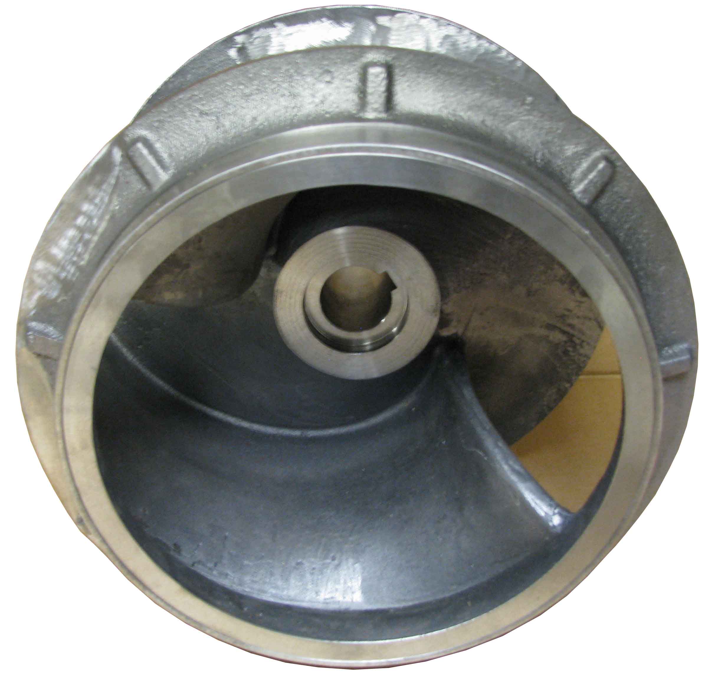
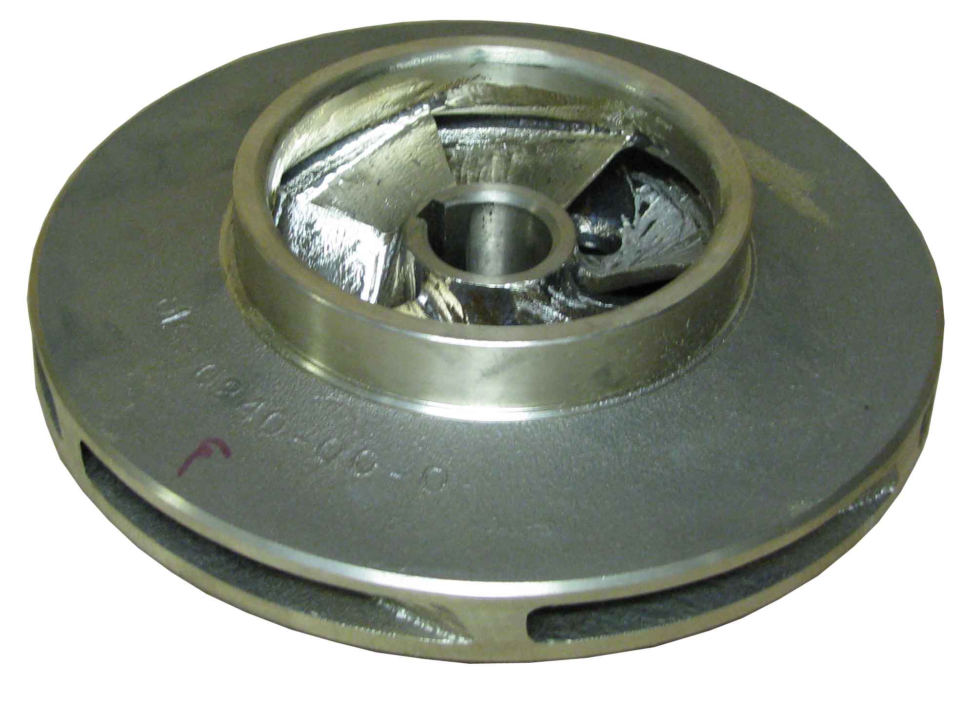 1) High Head Closed Channel Impeller – high-efficiency design for pumping water and other liquids at higher head pressures

2) Vortex Impeller – Used for pumping stringy solids and debris-laden liquids
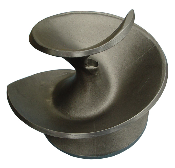
3) Centrifugal Screw Impeller – Used for pumping oils and other viscous liquids
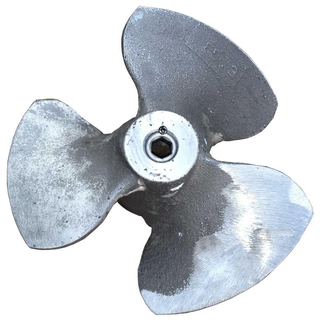
4) Propeller – Used for pumping high volumes of water at low heads
5) Shredder Impeller – Used for chopping solids to smaller pieces when they enter the pump
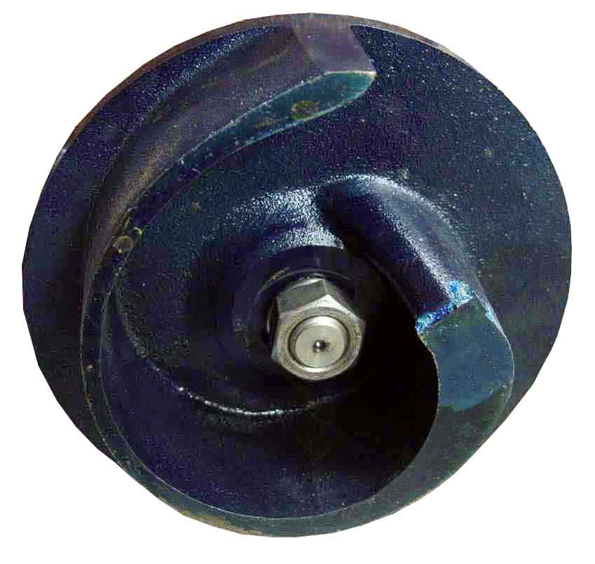
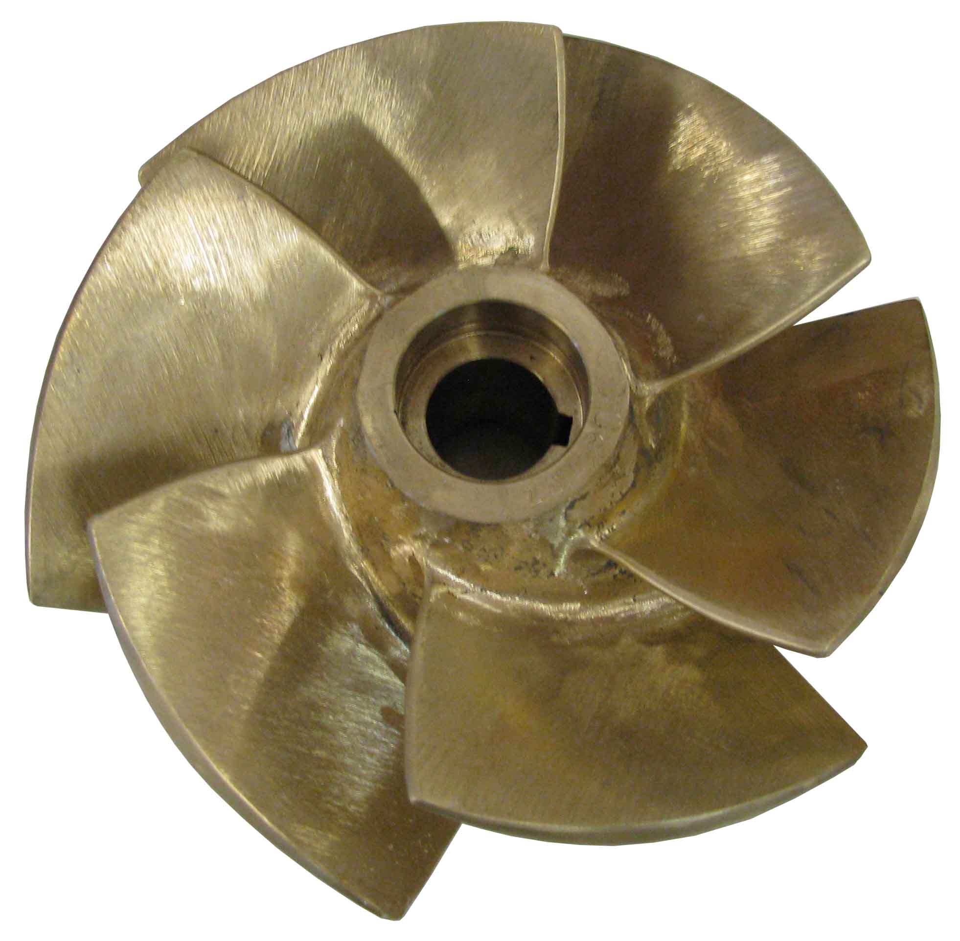
6) Closed Channel Impeller – Used for pumping sewage and wastewater
7) Mixed Flow Impeller – Used for high volume water pumping at low to medium heads
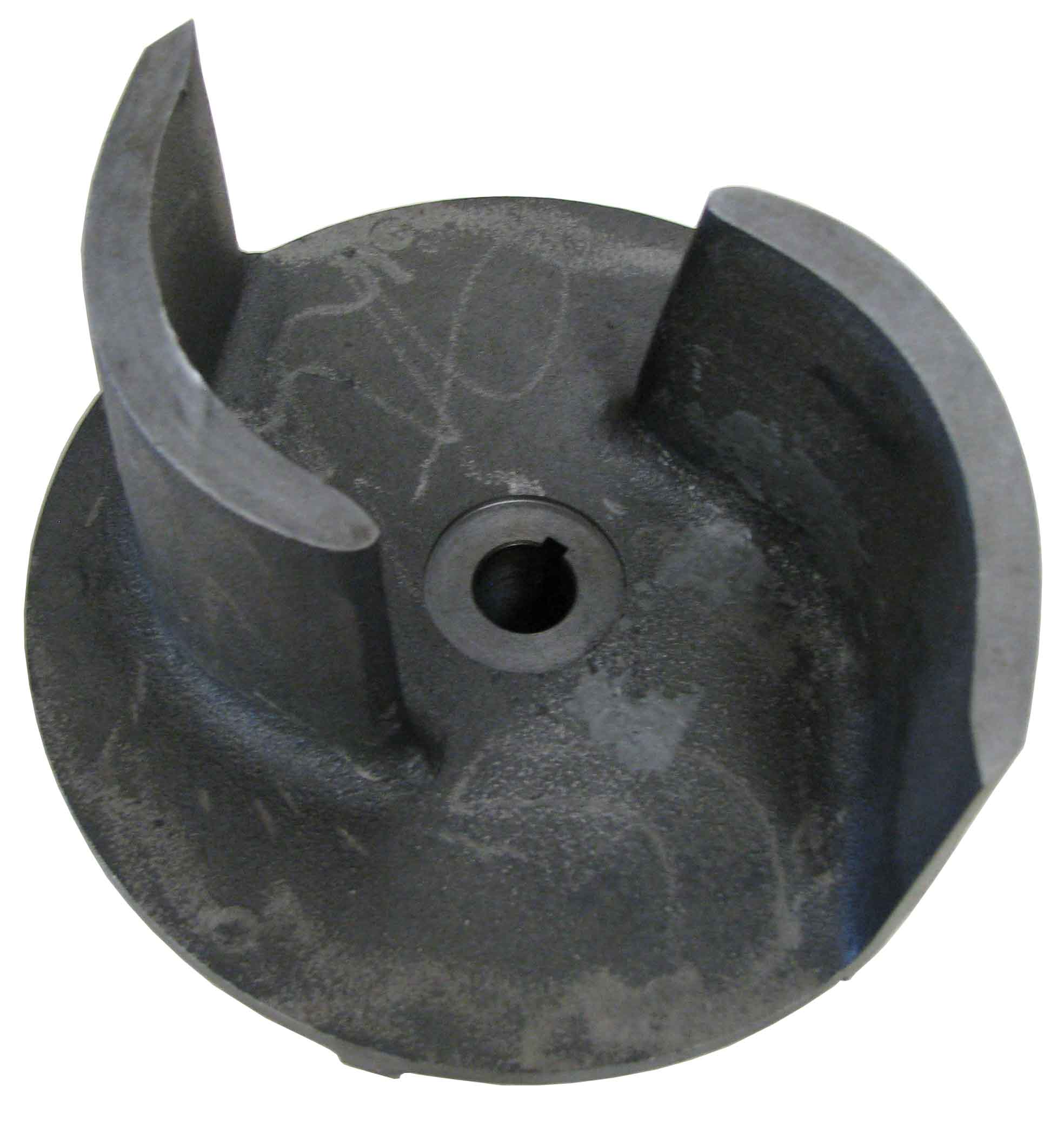
8) Semi-Open Impeller – Used for trash and debris laden liquids
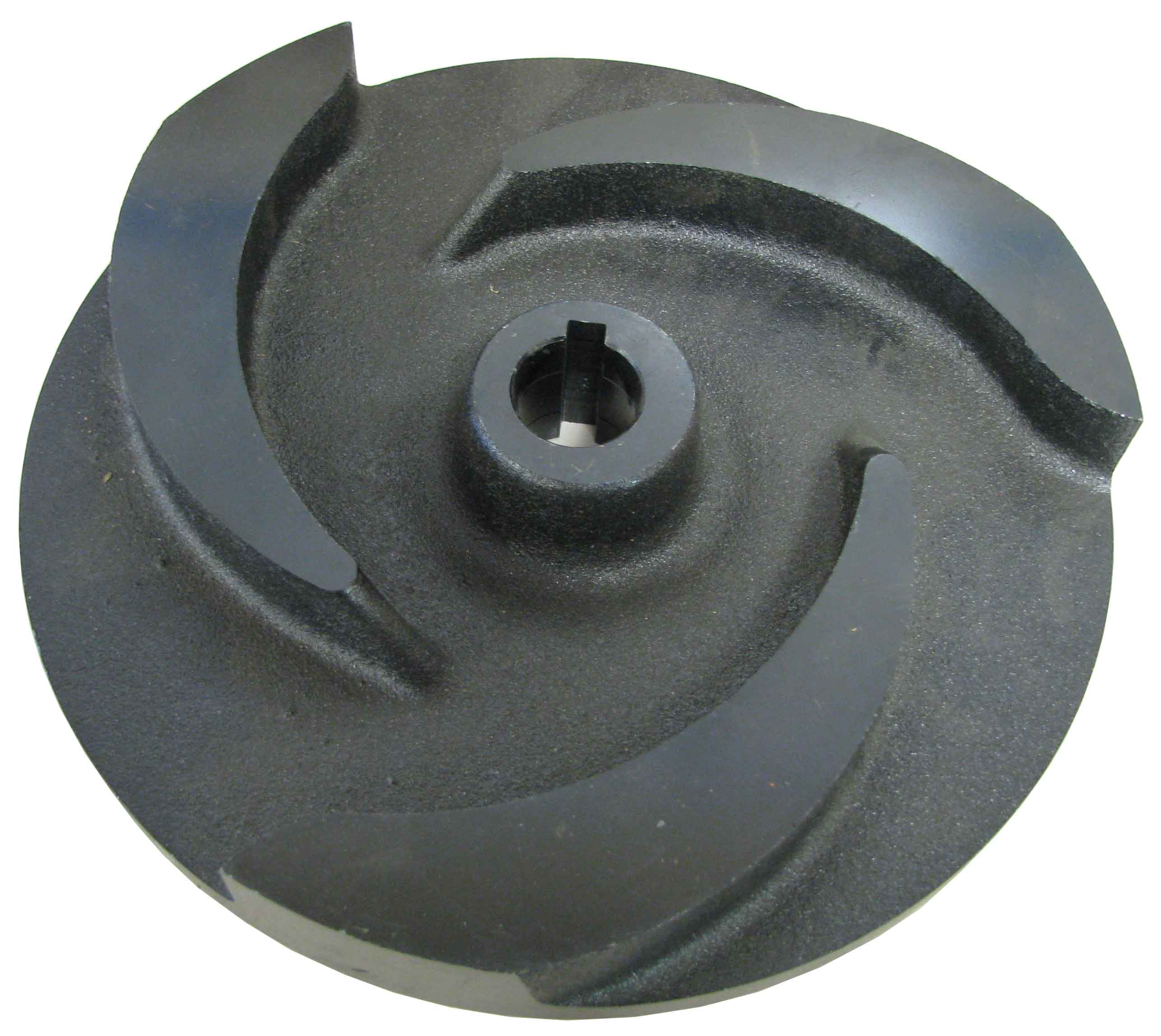
9) Hardened Sand/Slurry Impeller – Used for pumping abrasive liquids
A common question asked by Hydra-Tech customers is:
Why is there a small stream of water flowing from the top cover of my pump?
There is a logical answer to this, and it is not that the pump is broken. Hydra-Tech Pumps manufactures one (1) of the four (4) bolts used to hold the water plate in place. This bolt has a 1/8″ hole through the center of it. The purpose is to allow trapped air to escape from the volute (pump body) when placing the pump into the liquid for the first time.
Maintenance: If this hole gets clogged, you simply just push a pick through the hole to clean out the dried up debris.
Pumps are mechanical devices used to move a liquid from one place to another. On the most basic level, without allowing for friction losses, the difference in altitude from place A to place B is called the pump head requirement. It is measured in linear units such as feet or meters. The flow of the pump is measured in volumes per unit time, such liters per minute or US gallons per minute. The pump curve shows the relationship between these two measurements.
Here is an example of a curve and how to interpret it.

Head– height of liquid column is on the y-axis or vertical axis
We calculate feet of head to see how much pressure (psi=feet of head /2.31) the pump must overcome to deliver the resulting output flow at the delivery point.
Capacity– volume of liquid, is on the x-axis or horizontal axis
**Make sure you take notice to the unit of measure each one is being measured in. **
This point is showing this particular pump can supply 210 GPM @ 45 feet of head
You will notice each line is labeled from A-D, this is showing the different hydraulic inputs needed to make the pump run at the different levels of efficiency.
For example, in order to get your pump to pump 75 GPM @ 50 feet of head you would need a hydraulic unit able to provide 6 GPM @ 1500-2100 PSI, which you can find at Hydra-Tech Pumps with their HT13G portable hydraulic power unit.
*The maximum shutoff head (where all flow stops) of this pump is 75 feet. The best efficiency point of the pump would be about 85% of the maximum shutoff head. So at 64 feet the pump would be running most efficiently.